Volgende: Conclusions Omhoog: Technical implementation of the Vorige: The bcoWeb development tool Inhoudsopgave
First, the implementation aspects of web services are introduced, followed by a first test of dealing with semantic integration. Third, bcoWeb model checkers that, as web services, help maintain bcoWeb content. Web services that consume, use and augment bcoWeb content are described last.
As the proof of the pudding is in the eating, the next chapter presents cases. BcoWeb is an important ingredient, but such an Ontology network needs to be used in order to show its value. So this section looks into applications of bcoWeb. An interesting type of applications are the so-called `web services'. Web services are computer applications that usually reside on the machine of their owner and produce some service on data send to them over the Internet. Ideally there is no human activity involved (though human involvement still will be required in many cases).
Within a week of adding the Ontology download option (see figure 7.5 for an example output) to bcoWeb, a fellow researcher created a small Java desktop application [117] that could download this file and present its contents in a Java user interface. By working client-side, the responsiveness of the user interface was much better. This work was not known to the bcoWeb authors until finished, showing that NG Internet allows unthought-of new usages of the information to spring up [118].
An interesting feature of web based software for users is that they don't necessarily have to buy a license for application software. Providers can allow them to only pay for actual usage of software (mostly a modest sum). For software providers it might be an interesting addition to existing business, because casual users and small users will usually not buy an expensive license.
Web services allow applications to use functionality provided by other applications. So the advantages of web based software are extended from humans to computers.
One of the most important features of this type of web services is that, if based on a common Ontology like bcoWeb, by definition, they can communicate and co-operate. Until now application software has been developed in isolation. System designers selected the objects of interest most applicable for the application and developed complex data structures including the definitions of the objects of interest. Co-operation with other applications could not really be considered during the design. So, integration was left to be accomplished (if possible) afterwards.
The next paragraphs present a first test at creating software for a semantic integration of Specifications and Ontologies.
Chapter 8 describes the case in which a first test was done on integrating Specifications and Ontologies. The aim was to generate a Specification from an Ontology-based project description, with project description and Ontology both being available on-line. The Specification should also be available for the project tool for display to the user. In the end, the on-line part was foregone9.5, but the rest of the test remained and gave useful insight in the semantic integration process.
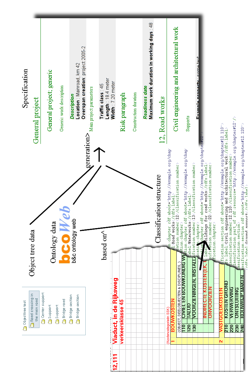
Starting point for development was a text-based STABU Specification which was converted into an XML-formatted file (using a variety of unix text conversion tools). The XML was transformed (using XSLT) into two separate semantic web RDF files, one for the Specification's chapter structure and one for the actual Specification items content. The separation was done to reflect the difference in semantic character between Classification data (chapter structure) and Specification data. Note that this is also reflected in the UML diagram of STABU's Specification system, figure 3.3. The Classification file contained links to individual Specification items, so that the Specification could be re-assembled.
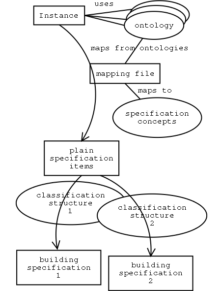
The project description was an RDF file pointing to concepts in the Ontologies used. To generate a Specification from the project description, the correct way is to do the coupling via the Ontologies. For this coupling, a mapping file was created plus a program to perform the mapping based on the mapping file. Figure 7.6 provides an overview.
 |
 |
A file was created that specified the mapping between concepts in the Ontologies and Specification items. For example, `House' is the starting point. The mapping file specifies that for the opening section of the Specification, naming the project, the address and the description of the house have to be extracted from the project file. This mapping was, of course, done in RDF.
The mapping used both `push' and `pull'. The Specification `pulls' the info needed in the opening section (the house's address, the house's description) from the project file. But it just reacts (`push') on a lot of other items. It only includes a section on brick walls when the project file `pushes' the brick wall to the mapper.
In a way, this simple solution mimics XSLT's behaviour. For the program that performs the mapping, experience with the behaviour of XSLT processors could be re-used.
The result of the mapping process is an RDF file with just Specification items, but without chapter structure. A small program adds the relevant chapters from the separate chapter RDF file, generated previously. This is converted to HTML at the end. Figure 7.7 tries to give an impression.
An interesting addition to this process was the conversion of the Dutch SfB Classification table (nl-SfB, elementenmethode) to a similar chapter structure file and adding the links from chapters to Specification items. Without changing anything regarding the original data, this second chapter structure could be combined with the resulting Specification items and transformed to HTML as an alternative building Specification.
Concluding, linking information with RDF works well. You can connect items together in a one-directional way, without needing mutual coordination. It is possible to flexibly add extra information (like, for instance, a second Classification structure) to existing information. The implementation, however, was small-scale and not itself accessible on-line, so apart from the above points, no extra conclusions can be drawn.
There is another advantage to supporting a NG Internet way of working. The FU/TS model--as implemented--is very simple. This does not mean, however, that the need for quality and coordination vanishes, which could be built directly into a more elaborate model. By being able to access the data externally, external supporting programs can check the available data for inconsistencies and omissions. Three of those programs have been implemented: to check for double names, for possible use of available abstract technical solutions (see figure 7.8) and for duplicate names (which means candidates for merging).
Upon the simple model explained earlier in this chapter, it is easy to build additional tools. Those tools are, in fact, what makes the simple model possible. The problem as such remains hard, but the hardness should be transferred as much as possible to the programmer, not to the volunteer that works with bcoWeb.
At the core of a bcoWeb approach is the Internet-based exchange of meaningful data. Within the prototype, RDF is used as the format in which to exchange most of the data. Therefore a means to read and interpret and query RDF is needed.
 |
A choice was made to use Python's rdflib, a simple RDF store that parses, stores, queries and exports RDF files [8]. It has the added benefit of being able to use the ZODB for storage.
For this research, a Zope product was created that turned rdflib into an integrated part of Zope. The UML diagram is shown in figure 7.9. A difficulty that needed to be overcome was to adapt rdflib, which uses some new Python techniques9.6, to Zope, which couldn't yet handle the new techniques.
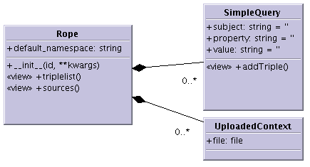
Rope can be used directly, allowing you to upload RDF files and to add simple queries. As this direct functionality is quite restricted, a common way will be to use Rope through subclassing it from another product. This route has been chosen in SimpleCat, described below, for instance.
The name chosen, Rope, reflects the combination of rdflib and Zope. The software is available at [119].
For the showcase in the next chapter, the Ontology's data needs to be enhanced with properties like width and length. Adding properties to the Ontology can be done in a number of ways. Allowing addition of properties into the core bcoWeb editor is a possibility, but you can also do it separately. For interoperability, the addition of properties directly to bcoWeb seems best. For the prototype development, the properties were added by hand in a separate file (see figure 7.10 for the contents of that file). For the way the prototype works, there is no material difference, though. One RDF file more or less doesn't make a difference.
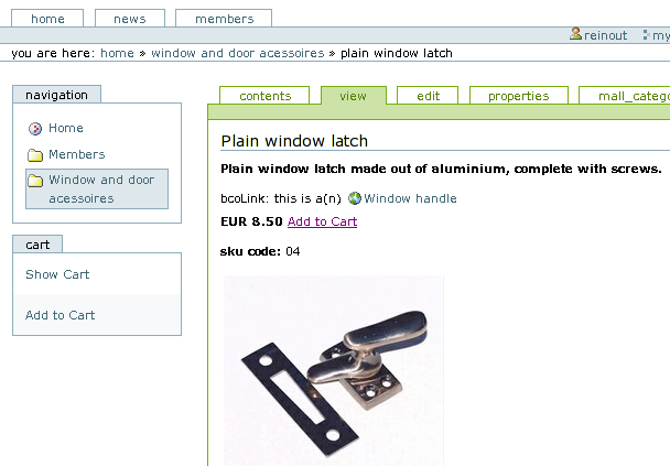
SimpleCat is a simple prototype for a bcoWeb-based catalog application. Its initial aim is to both consume and provide bcoWeb-based data in order to demonstrate bcoWeb's feasibility. Figure 7.11 shows the result.
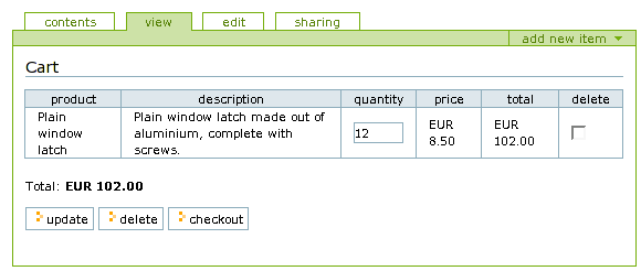
As the base for the implementation a Plone shopping framework, PloneMall [120], was used. PloneMall provides the main mechanisms for catalogs, categories, catalog items and even shopping carts (figure 7.12), tax handling and payment systems. Note that the shopping cart and payment systems didn't receive any attention during the implementation, but it does strengthen the expressibility of the prototype.
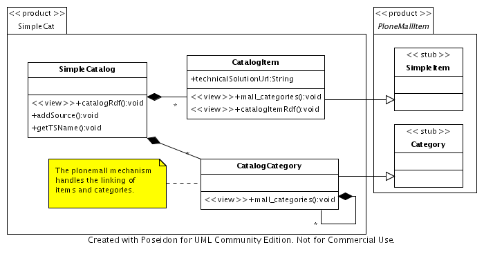
As a technically interesting point, PloneMall uses ArchGenXML UML code generation. This way, there is always an up-to-date UML model that documents the product. As SimpleCat also uses ArchGenXML code generation (figure 7.13), this was a good fit.
SimpleCat uses Rope (see section 7.4.4) to read bcoWeb Ontology files. These files are used for connecting the catalog items to bcoWeb Ontology items and for getting the names and properties of the Ontology items.
The connection between catalog items and Ontology items is the RDF/OWL subclass relation. An Ontology can contain a FU `window latch' which has as a TS `window handle'. A catalog offering various `window handles' is not really offering a completely new technical solution, its window handles are more a `kind of' TS window handle. That is why in this case the subclass relation has been chosen, which offers precisely the `kind of' Semantics desired. If the catalog item really is a new TS, it can be declared as such and used as a separate TS next to the other TSs.
The catalog application can, of course, export its contents as RDF again: figure 7.14.
The goal of ObjectTree is to demonstrate the use of bcoWeb and web-based data in a project setting. ObjectTree allows you to specify a project as parts that consists of subparts and so on. Those parts can be just locally used items or they can be taken from a bcoWeb Ontology.
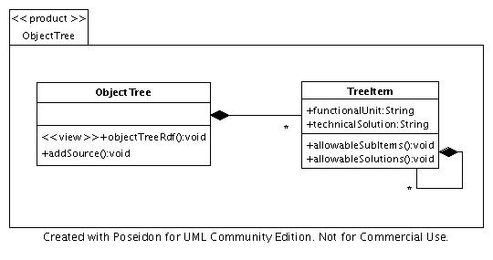
Like the catalog application, the tree instantiator uses the Rope RDF library as a back-end. This way, the application has access to bcoWeb Ontologies that can be used to assist in creating the object tree. Figure 7.15 shows the UML diagram that was used to generate the simple application with ArchGenXML.
It is possible to add TreeItems without using the bcoWeb functionality, in this way an object tree as described in [93] can be made.
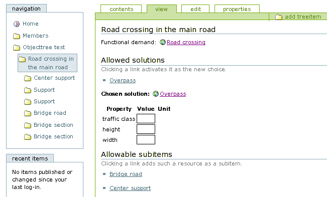
To use the bcoWeb-provided Ontology functionality, you have to link a TreeItem to a FU, signifying that the TreeItem tries to answer that particular functional demand. The RDF library is queried for possible solutions, which can then be chosen. For a chosen TS, the FUs that the TS consists of are displayed as possible subitems for the object tree. Clicking them adds them as a subitem, see figure 7.16.
 |
Using bcoWeb in this manner brings home the interactiveness of the underlying FU/TS model. It is a very natural model for supporting design and specification work. A question is provided along with possible answers, answers in turn lead to further questions. Multiple levels of detail can be covered in this way, without forcing anyone to specify every detailed item, as the interaction can be broken off at any level.
ObjectTree makes its data available as an RDF file, so that other applications can always download the up-to-date project information: figure 7.17. This possibility is used a few times in this thesis, see figure 7.7.